Wednesday 28 July 2010

Testing

I have been doing some testing on the standard 15mm speed fit tap value for potential use as an input pressure restricting method.
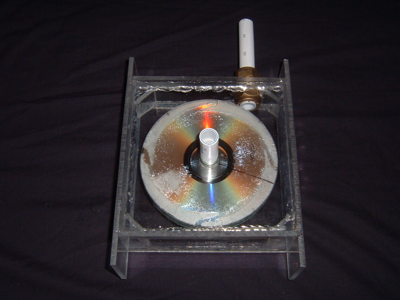
  I didn't hold out much hope for them but as they are cheap I thought I would try one. I used epoxy to glue a standard airline fitting into a speed fit connector. After this a small bit of speed fit pipe was inserted into the other end and then that then inserted into the test valve.
  The airline was connected up and the valve closed. The compressor was turned on and allowed to build pressure.  During pressure build I opened and closed the valve and although it acted fine it wasn't very easy to get a small amount of pressure flowing. It was very easy to get all or nothing.
  I set the value to the off position once again and let the pressure continue to build. Standing well back at this point I nervously waited for the compressor to cut out meaning that it was at its max. Unfortunately it was at this point my decision to stand well back was justified as the valve couldn't take the pressure before and blew up with quite an impressive bang followed by a lot of hissing!
  I really need a valve that will handle all the pressure so I can be certain that I can shut off the turbine at any point and be safe. I have spotted some brass valves with nice long handles on which should make for easier fine adjustment. I will pick one out, get it tested and report back. 

Monday 19 July 2010

After having a big think about things at the weekend I postponed making the connector between the compressor and the turbine. I had a quick thought when looking into what compressor I have access to. Its huge and by nature contains  massive pressure, once connected this is unregulated. Putting that much pressure through the plastic glued turbine all in one go will very probably cause it to explode and cover me in little bits of sharp plastic! I therefore need a way of regulating the pressure so some form of valve is in order. Ive looked at a couple of places so far trying to find a suitable off the shelf unit but so far nothing suitable. Ill update once I have found something :)

Thursday 15 July 2010

Its finally assembled !

I finally managed to get the time to assemble the turbine into the housing after first fitting the input tube in. After that I sealed it all using the silicone and let it set. The following pictures show the completed unit from various angles, note the marks on the turbine where I had to remove the edge disk and take off the spacers I put on the wrong way (Still annoyed with myself over that!)

Next stage is to get a loan of a compressor and see what connector it has on its output. I will then need to make a converter between that and the 15mm speedfit input of the turbine.
Hopefully I will be able to get on with that task for a portion of this weekend, fingers crossed :) Darren

Tuesday 13 July 2010

Spacers

Ooops mistake! whilst checking things over before assembling the whole thing I noticed I had fitted the spacers the wrong way round between two of the disks. To sort this out I had to carefully use a knife to cut through the glue and separate the disks away. The spacers got trashed in the process and Im out of spares. Its annoying but the unit should still work with one less disk/spacer. I have now glued a new endplate on and Im waiting for it to set before starting the assembly.

One the up side I have fitted the input pipe as detailed in the previous post and sealed it with some wicks all weather silicone sealant.

Monday 12 July 2010

Turbine input fitting

I have now drilled out the pilot hole to 20mm using a step drill from halfords :-
http://www.halfords.com   cat code 192393
This allows insertion of the 15mm compression pipe connector by removing the olive from one side, putting the thread through the hole in the ABS then putting the nut back on. After tightening up its nice and solid in place :-

From the top
From the underside  (looking up from inside the turbine housing
Next stages are to use the olive still left in the top of the fitting to mount a section of 15mm speedfit. This will allow easy fitting of tubing using off the shelf plumbing parts to plumb it into the compressor or air source. After fitting this tube I will seal round the fitting inside and out with silicone and also fit the turbine into its housing and seal that in. Once the sealant is set the unit will be in a state to test and find out if all of this has been a bit of a road to knowwhere :)

Thursday 1 July 2010

We here are the promised photos, not that good quality so I will try to replace them at some point will better quality ones.

This pic shows the initial template of the spacer I made for keeping the disks apart whilst allowing airflow. Also shown is the 15mm pipe and pipe insert used as the rotor mount.

This is the completed rotor with a line marked on it in permanent pen to better show spinning.

Heres the completed turbine housing without the front cover installed. Notice the 15mm speedfit pipe and insert protruding through the middle and the space mounts in the four corners.
This is a top shot of the housing with the rotor mounted with the front panel on. I have drilled a hole through the top which I will be expanding out to fit the air intake pipe.
This top shot better shows the pilot hole.
The above two show the turbine in its housing with from different angles.
Thats all for tonight :)