Showing posts with label Tesla Turbine. Show all posts

Sunday, 11 September 2011

The turbine works

One thing I did manage to get out my huge pile of stacked boxes is the tesla turbine variation I had been working on. It suffered some knocks in transit which resulted in the turbine rotor splitting into two sections. This wasnt a major problem but it did take some time to unseal the turbine housing and get it out.

I then had to go find new glue and sealant which is something I took for granted back in the Uk. As you live in a place for time you get to know where to find hardware you need and take it for granted that you can get it with ease. Over here in a new city and country all the things I need are here I just dont know where to find them!

After glueing the rotor back together and leaving under a pile of books while it dried I put it back in the housing and resealed it. At this point I thought I was ready to test and as I had access to a compressor I thought all systems where go. I was wrong, I wasnt ready in another quirk of UK to AU conversion, I should have realised that the compressor fittings are different over here than they are over in the UK. Some more investigation into the type and where I could get one it was a simple task to unscrew the jubalee clip and fit the new fitting.

Then I was ready :) I got the compressor fired up and waited until I had a full tank before connecting the turbine and slowly opening the valve. It works, the idea works! Its not well balanced, the rotor flaps back and forth quite a bit. Sometimes it needed a little encoragement to start to spin (I didnt want to just open the valve all the way, the pressure would pop the housing) Generally all these things where due to it having a lack of precision in the build but it actually spins. Im confident that if it was built with some engineering tolerences and a output power shaft introduced then rotational power could be extracted.

So due to my current circumstances this project is now shelved. I am having a little think about it from time to time about how best to build the better engineered one but for now the folloing video is about as far as its going to get.


If any of you make one then let me know I would love to see it and I would be happy to link to your site.

Tuesday, 12 April 2011

Apologies for the large amounts of nothing happening

  Sorry for the large large halt in anything happening here for the last eight months. It really does not feel like that long since my last post but the dates don't lie! I have spent the time organising, packing, finishing things and relocating to Australia. I have been over here about four weeks now and starting to settle in. More or less everything I own is now in transit on a ship somewhere, Im just hoping it makes it here in one piece!

  On the up side when I was tidying things up I rediscovered lots of things :) Amongst this I found the original circuit diagram for running a 12 volt battery up to the kind of voltage and pulses required for creating a very satisfying spark arc when run into a standard car distributor coil.

  Now Im almost on top of all the official paperwork that needed to be done to be here I will collate what I have tried and built for the hydrogen splitting experiments and get that up online. Once my boxes arrive and I have my equipment up and running I will at long last be able to test the modified Tesla turbine.

  One area Im very much looking forward to looking into now Im here is anything to do with the sun. There is quite a bit of it (which makes a nice change!) and it seems so underused as a power source. PV cells are great if you can afford them but the power you get back for the cost is huge. They are also not exactly something you can create yourself in your garage or shed. Im having a think about it, I will let you know what I come up with.

Thats all for now (but still loads more than you have had for ages :)

Tuesday, 10 August 2010

Not much progress really but here are a couple of photos of the new valve installed on the top of the turbine.

Tuesday, 3 August 2010

New valve

Bought a new valve tonight which should do the job. I finally settled on a 15mm gas valve from B+Q www.diy.com
It was in the gas fittings section and described as 'gas lever valve 15mm'. It has 15mm compression fittings on both sides so it should easily fit the rest it the setup and its a nice chromed metal design so it should take the presure.
Next step is to plumb it into the compressor fitting on one side and the turbine on the other. Hopefully this should happen either in the evenings this week or next. Im out this weekend and work is really getting in the way the rest of the time!

With any luck testing shouldnt be to far away. I was thinking about it all earlier and if this turbine design doesnt work I might build one as close to the Tesla design that I can and use the same housing. This will mean a slight redesign of the input so that its a nozzle but it will be much quicker than having to rebuild the entire turbine housing. It wouldnt have a power take off but it would be nice to see something spinning :) Then again there are plenty of other projects I want to investigate and so little time :) I am aware I still havent documented the Stan Meyers hydrogen stuff and woodgas turbo stove research I have done. Sorry to all those who visited the site wanting to read these sections. I will get round to it honest! Probably do the woodgas turbo stove first as its the simpler to explain and document.  The hydrogen section is a bit trickier requiring cylinder construction, low voltage electrolysis/electrode design and high voltage work all with circuit diagrams and explanations.

Wednesday, 28 July 2010

Testing

I have been doing some testing on the standard 15mm speed fit tap value for potential use as an input pressure restricting method.
  I didn't hold out much hope for them but as they are cheap I thought I would try one. I used epoxy to glue a standard airline fitting into a speed fit connector. After this a small bit of speed fit pipe was inserted into the other end and then that then inserted into the test valve.
  The airline was connected up and the valve closed. The compressor was turned on and allowed to build pressure.  During pressure build I opened and closed the valve and although it acted fine it wasn't very easy to get a small amount of pressure flowing. It was very easy to get all or nothing.
  I set the value to the off position once again and let the pressure continue to build. Standing well back at this point I nervously waited for the compressor to cut out meaning that it was at its max. Unfortunately it was at this point my decision to stand well back was justified as the valve couldn't take the pressure before and blew up with quite an impressive bang followed by a lot of hissing!
  I really need a valve that will handle all the pressure so I can be certain that I can shut off the turbine at any point and be safe. I have spotted some brass valves with nice long handles on which should make for easier fine adjustment. I will pick one out, get it tested and report back. 

Monday, 19 July 2010

After having a big think about things at the weekend I postponed making the connector between the compressor and the turbine. I had a quick thought when looking into what compressor I have access to. Its huge and by nature contains  massive pressure, once connected this is unregulated. Putting that much pressure through the plastic glued turbine all in one go will very probably cause it to explode and cover me in little bits of sharp plastic! I therefore need a way of regulating the pressure so some form of valve is in order. Ive looked at a couple of places so far trying to find a suitable off the shelf unit but so far nothing suitable. Ill update once I have found something :)

Thursday, 15 July 2010

Its finally assembled !

I finally managed to get the time to assemble the turbine into the housing after first fitting the input tube in. After that I sealed it all using the silicone and let it set. The following pictures show the completed unit from various angles, note the marks on the turbine where I had to remove the edge disk and take off the spacers I put on the wrong way (Still annoyed with myself over that!)

Next stage is to get a loan of a compressor and see what connector it has on its output. I will then need to make a converter between that and the 15mm speedfit input of the turbine.
Hopefully I will be able to get on with that task for a portion of this weekend, fingers crossed :) Darren

Tuesday, 13 July 2010

Spacers

Ooops mistake! whilst checking things over before assembling the whole thing I noticed I had fitted the spacers the wrong way round between two of the disks. To sort this out I had to carefully use a knife to cut through the glue and separate the disks away. The spacers got trashed in the process and Im out of spares. Its annoying but the unit should still work with one less disk/spacer. I have now glued a new endplate on and Im waiting for it to set before starting the assembly.

One the up side I have fitted the input pipe as detailed in the previous post and sealed it with some wicks all weather silicone sealant.

Monday, 12 July 2010

Turbine input fitting

I have now drilled out the pilot hole to 20mm using a step drill from halfords :-
http://www.halfords.com   cat code 192393
This allows insertion of the 15mm compression pipe connector by removing the olive from one side, putting the thread through the hole in the ABS then putting the nut back on. After tightening up its nice and solid in place :-

From the top
From the underside  (looking up from inside the turbine housing
Next stages are to use the olive still left in the top of the fitting to mount a section of 15mm speedfit. This will allow easy fitting of tubing using off the shelf plumbing parts to plumb it into the compressor or air source. After fitting this tube I will seal round the fitting inside and out with silicone and also fit the turbine into its housing and seal that in. Once the sealant is set the unit will be in a state to test and find out if all of this has been a bit of a road to knowwhere :)

Thursday, 1 July 2010

We here are the promised photos, not that good quality so I will try to replace them at some point will better quality ones.

This pic shows the initial template of the spacer I made for keeping the disks apart whilst allowing airflow. Also shown is the 15mm pipe and pipe insert used as the rotor mount.

This is the completed rotor with a line marked on it in permanent pen to better show spinning.

Heres the completed turbine housing without the front cover installed. Notice the 15mm speedfit pipe and insert protruding through the middle and the space mounts in the four corners.
This is a top shot of the housing with the rotor mounted with the front panel on. I have drilled a hole through the top which I will be expanding out to fit the air intake pipe.
This top shot better shows the pilot hole.
The above two show the turbine in its housing with from different angles.
Thats all for tonight :)

Tuesday, 29 June 2010

Life and its little delays

Sorry about the wait for the pictures of the test turbine, things have taken a back seat for the last couple of weeks whilst we have been preparing for Glastonbury. What an amazing mind blowing festival that is! I recommend it to anyone whos into any kind of music or just likes a good party :) So tired now, I would advise anyone going to pace themselves a little better than we did ;)

Doing some web wandering and came across the following site :-
http://onestraw.wordpress.com/
Hes creating a mulch powered heating and methane unit using simple easily available parts and feedstock. Its all very cool and I would love to give it a go once I have the space so Im watching it closely.

One thing I did manage to think about was the input side of the turbine. I picked up a straight through 15mm brass compression pipe joint from B+Q (www.diy.com). I should be able to mount that through the side (top) of the turbine using one half of the connector without the olive. The other half can be used to fit the input pipe on using that sides olive with the whole thing being sealed with silicone.

Ok tonight's work is getting the camera operational and getting the pics of the turbine, next post should be them, promise :)

Sunday, 13 June 2010

Ok, After thinking about where to start for a bit it kind of makes sense to get up what i'm doing at the moment which is the tesla turbine and my theoretical improvements. First lets go through Teslas turbine :-

http://en.wikipedia.org/wiki/Tesla_turbine

Tesla found that a gas or fluid being forced between two closely spaced flat entities exhibited an adhesive drag on those entities. He than moved forward with this to design and build his first turbine. This consisted of a set of closely spaced flat disks held together with washer spacers between plates. The center of each disk had a wide hole and a cross shaped support joining the disk to a central shaft. Pressurized gas was forced in at the space between the disks at an angle where it spiraled towards the center of the disk and allowed out through the cross shaped support. I have attached a pic of Teslas design pic.

A photo of Tesla's own revolutionary turbine.Image via Wikipedia


···As a home researcher unfortunately I dont have access to some nice computational fluid dynamics packages that would be very useful here to calculate the gas flow through the turbine and hopefully see methods of improvements. The only methods available to me (and lots of other people I think) is stitting and thinking and then building it and seeing if it works. Lots of talented people have built up Tesla turbines and there are some very nice utube vids of them spooling up. It seemed a duplicated step to build one myself so after looking at many builds I sat and thought lots about it all.

···The key theory from Teslas boundary layer turbine seems to be that the gas is injected at the edge of the disks preferably using a nozzle assembly to inject it between them. Gas should then spiral in and exit the disk in the center. As the gas travels on its spiral towards the exit it exert its adhesive force onto the disks and the pull on them starts the disks spinning. My thoughts about this lead to the idea that the more uninterrupted the flow of gas from input to exit the better the transfer of power to the disks. Its known that a well designed nozzle inserting the gas between the disks works better than just inserting it across the whole outside of the disk array. This reduces external turbulence with gas flow injected where its needed.

···My potential improvement focuses on the central area of the disk where the gas exits between the disks and where in Teslas design the star shaped support is. In an ideal implementation (I think) the disks would be placed closely together with the gas injected at the edge and exit in the middle. The gas would have an uninterrupted flow through out its entire path.
···In teslas build the star shaped spacers at the centers of the disks only allow the gas to exit when it can get to one of the four sections where the star doesn't protrude from the center to the edge. In a test where the disk and therefore star was held stationary whilst the gas was injected the gas flow would stabilize to flow towards the center, bump into the protruding star supports, flow round them then exit. This would create flow eddies and areas where the because the spiral flow was not wholly spiral the power to the disks would be reduced.

···Now thinking about it as a spinning disk. If the gas injection flow is constant that central spinning star will create a slow moving obstacle at initial startup causing huge eddy flows. As the turbine spins up these eddies will change which will change the spiral gas flow and hamper power transfer. In (my) theory each size of turbine of this type would have an ideal gas flow rate where the input to the turbine matched the spinning star to the point where the gas flow was least impeded.

···So the theory is that disks with no supports in the center and spacers at the sides would work well for gas flow. Unfortunately holding the disks in this position and getting power output from them would be impossible (well for me anyway). I therefore had to think of a way of keeping the disks apart whilst holding them impeding the gas flow.

···What I came up with is the stack of disk would be held apart with spacers at their edges. The spacers will be shaped to allow gas in then 'aim' it towards the direction of flow to start the spiral. The centers of the disk would have no support between disks with the exit hole free to accept flow from all angles. The end two disks will have central pivot acting also as an exhaust for the gas. The disks will be encased in a chamber which is then pressurized. The gas gets pressured into the input holes between the disks spacers, from there directed sideways encouraging it to start its spiral flow to the center. At the end of the spiral it enters the center of the disk and heads sideways to the exhaust at the end. In my theory this will work :) I need to build one to test the idea it doesn't initially have to have a spinning output shaft, just spin the rotor which should make a build easier.

···As I dont have a nice machine shop of my own and I cannot justify spending out on getting a unit made just to test the theory I needed to make a test unit up using parts I could work with and bits I could get hold of. I settled on 8 cds for the disks as they are nice and flat, readily available and can be glued. My local plastics shop was nice enough to donate some abs plastic offcuts to the project. After looking into a few things to act as the central rotors/exhaust simple speedfit pipe and 2 pipe inserts offered the most readily available and cheapest solution available. I also bought from the plumber merchants some plastic glue of the type used to glue abs pipes together and some silicon sealant.
···Below are the dimensions for the turbine housing. The plastic was cut using a jigsaw from B+Q setup on a workbench using gclamps.


···To get the whole through the center of each end panel I marked out the center on one, clamped the two together then drilled through them both. I started with a small drill bit and expanded up to the 15mm that is the cd center size and the speedfit pipe size. After that I used the ABS pipe glue to glue together the housing sections, the two shorter end sections first followed by the longer ones. Using a bit of the speedfit pipe through the center of both end panels helped to hold the whole thing in position while the glue started to go off. In glueing it all together I only glued in one end panel allowing turbine insertion. After the glue had set overnight I glued in the corner braces which also act as spacers for the end panels. Another overnight glue set period happened.
···Next I chopped two twoish inch lengths of the speedfit pipe up and inserted a pipe insert into each. These where then inserted into the end panels with the inserts facing towards each other (to the center of the turbine housing) This was the housing nearly done, just the end panel to put into place once the turbines in and then silicone it in.

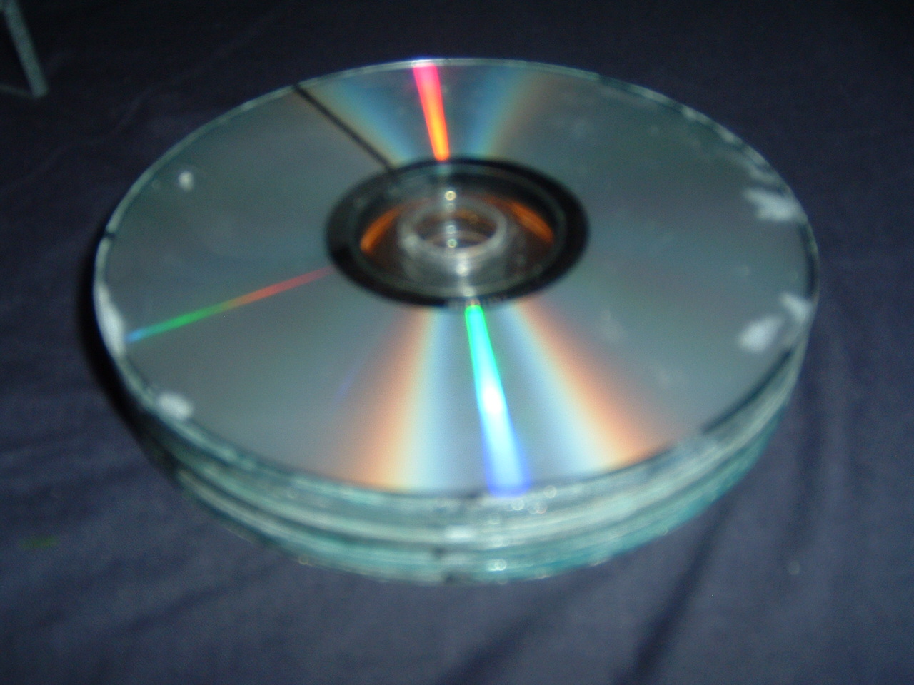
···Turbine parts where next and these where the trickyest to manufacture. Below is a diagram of the turbine spacer. I haven't taken the dimentions off it (tricky with all the curves) but basically its four of these per two disks (to act as spacers). These where cut out of more CDs using the jigsaw and lots of swearing! CDRW seem to work the best for cutting as the plastic is different than others as they dont seem to crack and shatter as much. After an age of cutting I ended up with the required 28 of these. Seven of the eight disks where now marked with a pen to provide starter marks where each of the four spacers would be glued from. The easiest way I found to do this was to mark a disk anywhere on its edge. Next use a ruler and measure 8.5cm across the disk and mark where it intersects the edge. Do this twice more and you should have four marks all 8.5cm away from each other. The spacers where then glued onto the disks and carefully compressed under a weight overnight. Next I got a cd pack case that usually holds a 100 disks and has a shaft up the center. One cd with the spacers glued to it was placed over the shaft with the spacers facing up. Glue was applied to the tops of the spacers and the next cd placed on top (again with the spacers facing up). Each cd was offset from the one below it by 90 degrees thus offsetting the inlets. After all the disks with spacers where placed the final disk was placed on the top followed by a load of weight and left overnight.


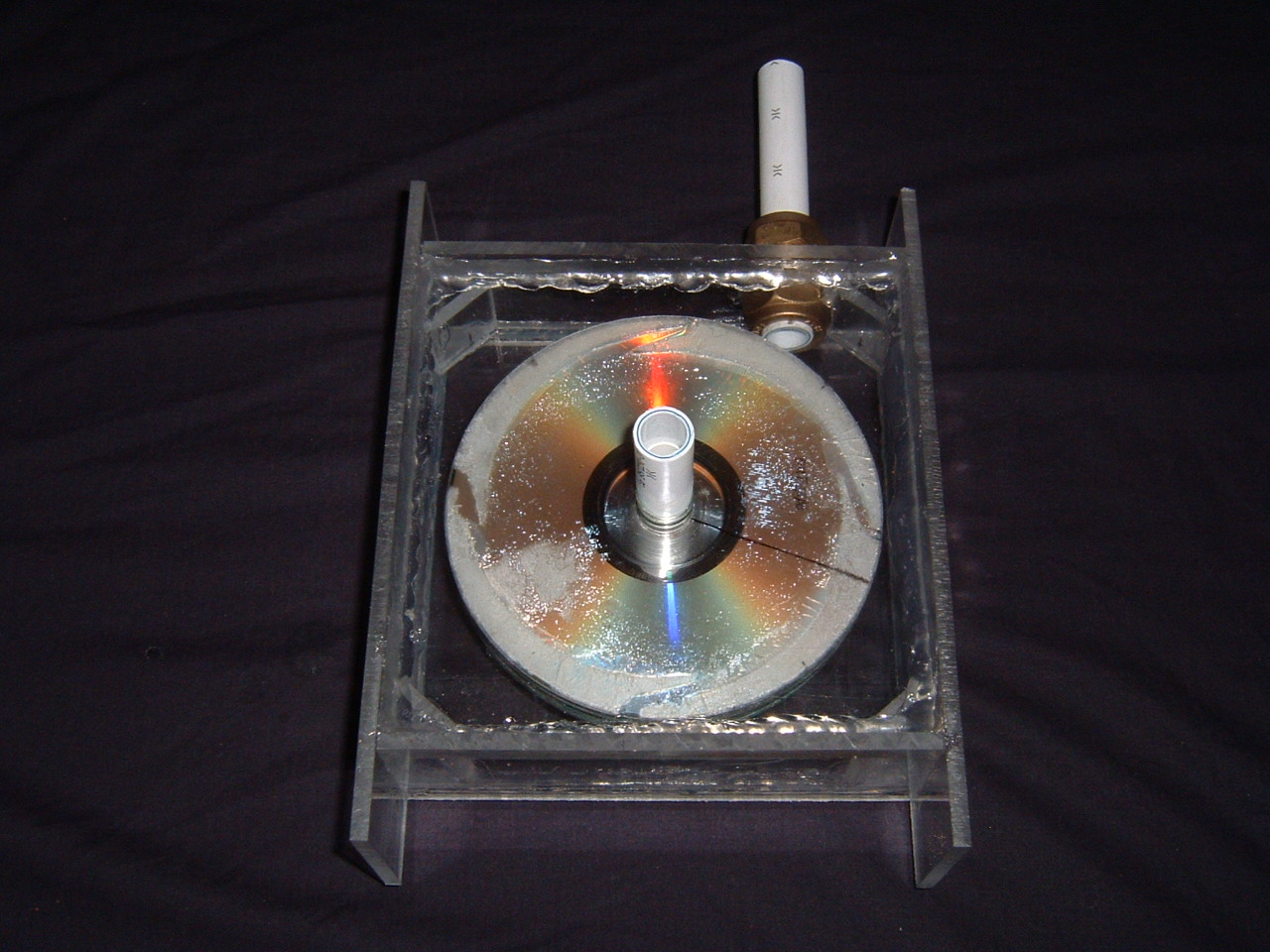
···The turbine complete I now placed it into the turbine housing placing the center of the end cd onto the speedfit pipe insert mounted in the rear panel. The front panel was fitted again lining up the center of the cd onto the pipe insert. The panel sits onto the housing corner supports which in turn sets the distance the panels are set apart. The speedfit pipes can be carefully pulled or pushed back and forth to set the inserts into the centers of the cds and increase or decrease the friction.

···An air intake is required so I thats what I need to work on next. I did think about drilling in another 15mm hole in the top of the turbine housing to accept a bit of speedfit but because of the plastic type of the pipe it wont glue with the glue Im using for the ABS. Im having a think about it hopefully something will spring to mind.

···The turbine spins freely given a twist of the housing which is promising. Soon I will need to borrow a air source such as a compressor, build up a valve and pipework to connect the two then try it. Im fully expecting this if it starts to spin to whizz round to the point where it jumps off the pipe inserts and the turbine impacts into the abs turbine housing. I fully intend to be standing far away at any point during testing this. If it does do this though I dont mind to much as it will have proved the theory. I will then look towards improving it and building another out of alloy with proper bearings and a power takeoff of some sort. Fingers crossed and I will report back.

I will get some photos of the turbine and housing sorted and get them posted over the next couple of days.

Saturday, 12 June 2010

Technologies - things I have already played with.

Tech I have already investigated is :-

Hydrogen production
Raw production using standard electric anode cathode in water approach.
After this I experimented with the work of Stanley Meyer and followers such as Dave Lawton. This work includes very high voltage arcing and pulse width modulation through the water with and without electrolytes.
This project needs more research and ideas throwing at it, I have a few ideas to try but as always I cannot do everything at once.

Gasifier
Played with a number of designs and builds looking into this relatively easily achieved technology. I also built up a very easy to build mini fan assisted gasifier sometime also known as a rocket stove. This achieves a very satisfying foot high flame out the top :)

Tesla turbine
This is very interesting and the most recent project that Im playing with. Im currently looking into building up a prototype unit implementing a modified rotor assembly than Tesla used in the plans I have seen.

I aim to expand on all the above work and publish it up here with a bit of a brain dump as to what I was thinking at the time I tried something. I will also be putting up photos of things and circuit diagrams I have/am using for things. Im based in the uk so where I can remember I will be posting where things can be bought. As Im doing this as a hobbyist and dont have the resources of those lucky people with cnc machines and laser cutters what Im doing should be relatively easy for anyone reading to copy.

Helpful comments and constructive criticism is welcome but please dont bother posting if you just going to be negative. Im doing this at I like to know how things work and hopefully to make a difference to someone somewhere. I take no responsibility for anyone damaging themselves or anything else whilst attempting to replicate anything I have built. Plans and theories for things are just that and I make no guarantee that they will work for you.

All the above being said however please join in with research into any of the above areas and if you find something out or see a obvious error in what I have done then please let me know :)

Right thats the second post finished lets see how this ends up as far as the formatting goes when I post it!