We here are the promised photos, not that good quality so I will try to replace them at some point will better quality ones.
This pic shows the initial template of the spacer I made for keeping the disks apart whilst allowing airflow. Also shown is the 15mm pipe and pipe insert used as the rotor mount.
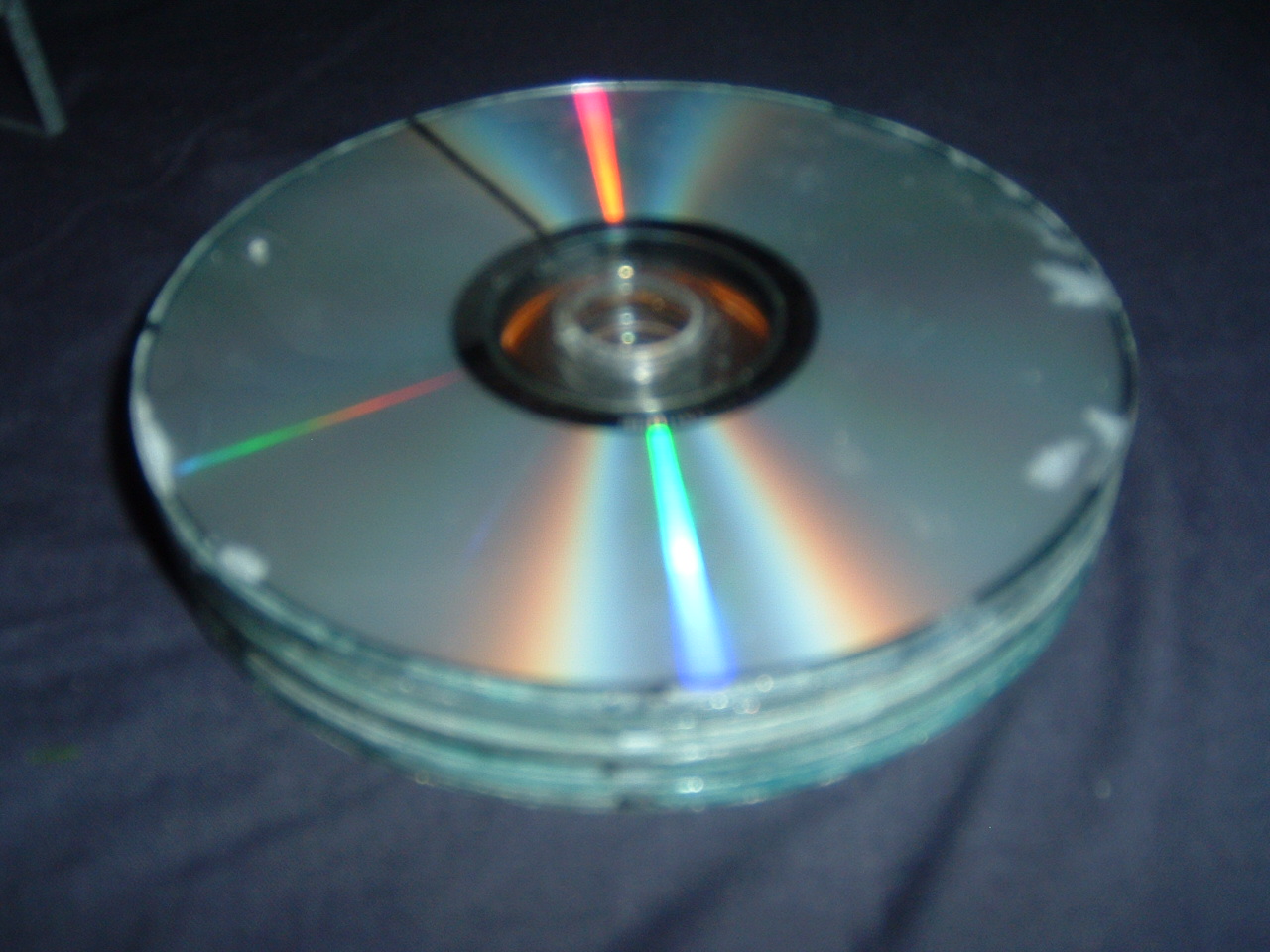
This is the completed rotor with a line marked on it in permanent pen to better show spinning.
Heres the completed turbine housing without the front cover installed. Notice the 15mm speedfit pipe and insert protruding through the middle and the space mounts in the four corners.
This is a top shot of the housing with the rotor mounted with the front panel on. I have drilled a hole through the top which I will be expanding out to fit the air intake pipe.
This top shot better shows the pilot hole.
The above two show the turbine in its housing with from different angles.
Thats all for tonight :)


No comments:
Post a Comment